Decompyled Speedo
Warning: This Mod could potentially be dangerous to your components if performed without extreme caution and knowledge of soldering. This mod should NOT be repeated. DO NOT ATTEMPT TO DO THIS, unless you can afford a new speedo if all goes wrong. Removing the speedo from the bike will cause your clock to reset as well as your trips, so remember how many miles you got to get to a gas station :). Don't worry, your Odometer will not be affected.

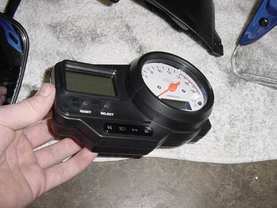
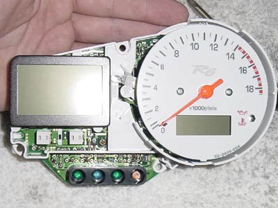
| The patient |
| 2002 Yamaha YZF-R6 |
| The surgery instruments |
|
|
| Parts Used |
|
**any other color is 4 volts and would require me to poke and prod my speed a lot more to find the correct voltage... sorry to all that want to make a red one to match your cherry R6. If I'm really bored one day ill do so :)** |
| Step 1: Speedo Removal |
| Remove the front cowl. This requires removing the mirrors if you don't already know. Disconnect the headlights and turns and set it off to the side. You should now be able to see the back of your speedo. 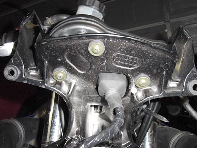 Remove the 3
screws holding to the frame and disconnect the harness. Remove the 3
screws holding to the frame and disconnect the harness. |
 Remove the Speedo from the frame and we are ready to
start the fun! Whoo hoo! Remove the Speedo from the frame and we are ready to
start the fun! Whoo hoo! |
| Step 2: The Speedo |
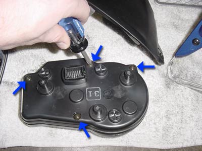 Flip the speedo over and you will find 4 more screws
holding it together. Flip the speedo over and you will find 4 more screws
holding it together.Remove these and carefully pry open the case with your hands. The first time you open the case, it will stick a little bit so be cautious not to jolt open the case and eject the innards onto the floor. |
 Here we see the backside of the circuit
board Here we see the backside of the circuit
board*Disregard the green and white wire in this photo. Its from my first attempt at the mod. You will see a black circular thing in the center when you open yours. This is the light we want to change. Give the light a slight counter-clockwise twist and it will pop out of the board. There are two lights back here but we only want to do the center one. The one near the corner lights up the back of the tach and a blue light wont work very well. |
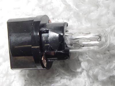 The Little bugger that we're replacing
:) The Little bugger that we're replacing
:) |
| Step 3: The LED (Light Emitting Diode) |
Next we must prepare the LED to hook up to our
circuit board. I bought this Blue LED from a local electronics store
for $4. I've been using it for other applications which is why it
looks kinda mangled :). Blue, White, or Turquoise LED's are commonly
run at 6volts so i had to check all over the circuit board to find a
suitable location to solder the leads to. After a couple hours and
hooking it up in several wrong locations, I finally found the sweet
spot :).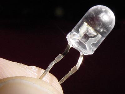 With incandescent lights polarity isn't important but in
LED's you must hook up positive to positive and negative to
negative. With incandescent lights polarity isn't important but in
LED's you must hook up positive to positive and negative to
negative.If you look at the photo of this LED you can see the two terminals that go inside of the plastic bulb. The large portion inside the bulb is the cathode (negative) and the small side is the anode (positive). Keeping in mind which side is negative(-) and which side is positive(+), connect your LED to your lead wires. I used a wire from an old computer case that indicates the computer is turned on. I simply switched the green bulb for the blue and trimmed the lead to length. 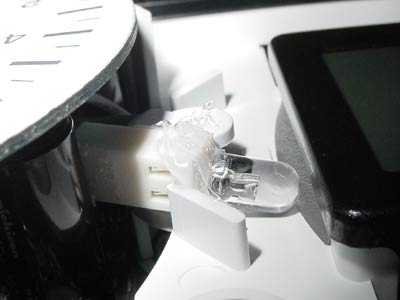 Position the
tip of the LED to point towards the LCD (speedometer) screen. There
is a small piece of beveled translucent plastic to the right of the
LCD. This is what disperses the light behind the speedo. The closer
you can get it to this the better. There is a piece of plastic that
will come down on top of this section when you replace the cover of
the speedo so be sure to keep the light in a position which it
doesn't interfere with closing the case. Position the
tip of the LED to point towards the LCD (speedometer) screen. There
is a small piece of beveled translucent plastic to the right of the
LCD. This is what disperses the light behind the speedo. The closer
you can get it to this the better. There is a piece of plastic that
will come down on top of this section when you replace the cover of
the speedo so be sure to keep the light in a position which it
doesn't interfere with closing the case.After you find a position that works, tack the bulb down with a gob of silicon sealant and let it dry. Then feed your lead wires through the hole of the original light bulb. |
 LED hooked up: ready to give it some
juice! LED hooked up: ready to give it some
juice! |
| Step 4: Soldering (Take your time) |
All right yall, this is it... the real tricky part.
One mistake could mean searching for a new speedo Gasssp! At least
then you could say "No really officer, I DON'T know how fast I was
going". So take your time and be very accurate. Remember the
terminals we are soldering to still contain other electronic
components that make your speedo function. So get the wire in place
and set as quick as possible, and don't let the iron touch the
contact for more than 1-2 seconds. Overheating the components could
mean destruction to the small semi-conductors on the board. That
being said, lets get started.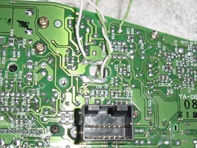 Click the
photo to see a larger, more detailed view. Click the
photo to see a larger, more detailed view.Start by stripping off 1/16 of an inch of insulation off your wire leads, and tin the exposed wire with your soldering iron (if you don't know how to tin a wire, undo everything you have just done and put your bike back together while it still works). Find the area on your board that matches this picture. Notice I have a green and white wire in the photo. The green is what I hooked up to the positive of my LED and the white is negative. Find the terminal for the positive lead on the board. Its the one right between resistor #58 (R58) and capacitor #28 (C28). Solder your positive LED lead here. The negative goes near the hole from the removed stock lamp. |
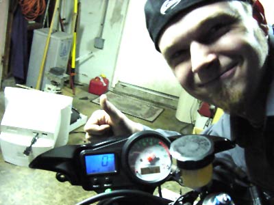
| Step 5: Testing & Conclusion |
 Plug the unit into the harness and throw the key. YAY!
BLUE! Assuming you did everything right, it should light up... if
not, something is wrong quickly turn off the bike and disconnect the
speedo from the harness. You may have hooked the LED up backwards.
Try reversing the leads and try again. If it still doesn't work I'd
suggest reverting back to the way it was and leaving it
alone. Plug the unit into the harness and throw the key. YAY!
BLUE! Assuming you did everything right, it should light up... if
not, something is wrong quickly turn off the bike and disconnect the
speedo from the harness. You may have hooked the LED up backwards.
Try reversing the leads and try again. If it still doesn't work I'd
suggest reverting back to the way it was and leaving it
alone.If it works, congrats! Put everything back together the way you took it apart and enjoy! |
 Gets the Decompyler seal of pimpin' more
chix! Gets the Decompyler seal of pimpin' more
chix! |
. . .